Shop By Department
- Central Vacuums
- Find Your Brand
- ACV
- Replacement Power Units
- Attachment Kits
- Floor Brushes
- Tools & Accessories
- Electric Powerheads
- ACV Air-Driven Turbo PowerHeads
- ACV Hoses
- ACV Hose Parts & Handles
- Wands
- ACV Bags
- ACV Filters
- ACV Motors
- ACV Carbon Brushes
- Wall Inlets
- Mufflers & Exhaust
- ACV Hardware and Safety
- Pipes & Fittings
- ACV Installation Kits
- Car & Garage
- Dustpans
- ACV Dust Mops
- ACV Belts & Brush Rollers
- ACV VacuBumpers
- Aggresor Central Vacuums
- Replacement Power Units
- Aggresor Attachment Kits
- Aggresor Floor Brushes
- Aggresor Tools & Accessories
- Aggresor Electric Powerheads
- Aggresor Air-Driven Turbo PowerHeads
- Aggresor Central Vacuum Hoses
- Aggresor Hose Parts & Handles
- Aggresor Wands
- Aggresor Central Vacuum Bags
- Aggresor Central Vacuum Motors
- Aggresor Central Vacuum Carbon Brushes
- Aggresor Central Vacuum Wall Inlets
- Aggresor Central Vacuum Mufflers & Exhaust
- Aggresor Central Vacuum Hardware and Safety
- Aggresor Central Vacuum Pipes & Fittings
- Aggresor Central Vacuum Installation Kits
- Aggresor Car & Garage Accessories
- Aggresor Central Vacuum Dustpans
- Aggresor Central Vacuum Dust Mops
- Aggresor Central Vacuum Belts & Brush Rollers
- Aggresor Central Vacuum VacuBumpers
- Air King Central Vacuums
- Replacement Power Units
- Attachment Kits
- Floor Brushes
- Tools & Accessories
- Electric Powerheads
- Air King Air-Driven Turbo PowerHeads
- Air King Hoses
- Air King Hose Parts & Handles
- Wands
- Air King Bags
- Motors
- Carbon Brushes
- Wall Inlets
- Mufflers & Exhaust
- Air King Hardware and Safety
- Pipes & Fittings
- Installation Kits
- Car & Garage
- Air King Dustpans
- Air King Dust Mops
- Air King Belts & Brush Rollers
- Air King VacuBumpers
- Airstream Central Vacuums
- Airstream Power Units
- Attachment Kits
- Floor Brushes
- Tools & Accessories
- Electric Powerheads
- Airstream Air-Driven Turbo PowerHeads
- Airstream Hoses
- Airstream Hose Parts & Handles
- Airstream Bags
- Pipes & Fittings
- Wall Inlets
- Airstream Hardware and Safety
- Mufflers & Exhaust
- Car & Garage
- Airstream Dust Mops
- Airstream Belts & Brush Rollers
- Airstream VacuBumpers
- Allegro Central Vacuums
- Replacement Power Units
- Attachment Kits
- Floor Brushes
- Tools & Accessories
- Electric Powerheads
- Allegro Air-Driven Turbo PowerHeads
- Allegro Central Vacuum Hoses
- Allegro Hose Parts & Handles
- Wands
- Allegro Central Vacuum Bags
- Allegro Filters
- Allegro Motors
- Allegro Carbon Brushes
- Wall Inlets
- Allegro Hardware and Safety
- Mufflers & Exhaust
- Pipes & Fittings
- Installation Kits
- Car & Garage
- Dustpans
- Allegro Dust Mops
- Allegro Belts & Brush Rollers
- Allegro VacuBumpers
- Motors
- AirVac Central Vacuums
- Replacement Power Units
- Attachment Kits
- Floor Brushes
- Tools & Accessories
- Electric Powerheads
- AirVac Air-Driven Turbo PowerHeads
- AirVac Hoses
- AirVac Hose Parts & Handles
- AirVac Wands
- AirVac Bags
- AirVac Filters
- Motors
- Carbon Brushes
- Wall Inlets
- Mufflers & Exhaust
- Hardware and Safety
- Pipes & Fittings
- Installation Kits
- Car & Garage
- Dustpans
- Dust Mops
- Belts & Brush Rollers
- VacuBumpers
- Airvac AVR 7500
- AirVac AVR12000
- Airvac AVR 3000
- Airvac AVR 24000
- Astrovac
- Replacement Power Units
- Attachment Kits
- Floor Brushes
- Tools & Accessories
- Electric Powerheads
- Air-Driven Turbo PowerHeads
- Hoses
- Hose Parts & Handles
- Wands
- Bags
- Filters
- Motors
- Carbon Brushes
- Wall Inlets
- Mufflers & Exhaust
- Hardware and Safety
- Pipes & Fittings
- Installation Kits
- Car & Garage
- Dustpans
- Dust Mops
- Belts & Brush Rollers
- VacuBumpers
- Beam
- Beam Power Units
- Attachment Kits
- Beam Floor Brushes
- Beam Tools & Accessories
- Beam Electric Powerheads
- Beam Air-Driven Turbo PowerHeads
- Beam Hoses
- Beam Hose Parts & Handles
- Beam Wands
- Beam Bags
- Beam Filters
- Beam Central Vacuum Motors
- Beam Carbon Brushes
- Wall Inlets
- Beam Hardware and Safety
- Mufflers & Exhaust
- Pipes & Fittings
- Installation Kits
- Car & Garage
- Dustpans
- Beam Dust Mops
- Beam Belts & Brush Rollers
- Beam VacuBumpers
- Beam Central Vacuum Circuit Boards and Relays
- Beam SC325
- Beam SC375
- Beam SC398
- Beam SC3500
- Beam SC200
- Beam 2775
- Beam 189
- Beam 284
- Black & Decker
- Replacement Power Units
- Attachment Kits
- Floor Brushes
- Tools & Accessories
- Electric PowerHeads
- Air-Driven Turbo PowerHeads
- Hoses
- Hose Parts & Handles
- Wands
- Bags
- Motors
- Carbon Brushes
- Hardware and Safety
- Wall Inlets
- Mufflers & Exhaust
- Pipes & Fittings
- Installation Kits
- Car & Garage
- Dustpans
- Dust Mops
- Belts & Brush Rollers
- VacuBumpers
- Broan
- Replacement Power Units
- Attachment Kits
- Floor Brushes
- Tools & Accessories
- Electric PowerHeads
- Air-Driven Turbo PowerHeads
- Hoses
- Hose Parts & Handles
- Wands
- Bags
- Filters
- Motors
- Carbon Brushes
- Wall Inlets
- Mufflers & Exhaust
- Hardware and Safety
- Pipes & Fittings
- Installation Kits
- Car & Garage
- Dustpans
- Dust Mops
- Belts & Brush Rollers
- VacuBumpers
- Brute
- Replacement Power Units
- Brute Attachment Kits
- Brute Floor Brushes
- Brute Tools & Accessories
- Brute Electric Powerheads
- Brute Air-Driven Powerheads
- Brute Hoses
- Hose Parts & Handles
- Brute Wands
- Brute Vacuum Bags
- Brute Vacuum Motors
- Carbon Brushes
- Brute Wall Inlets
- Hardware and Safety
- Brute Mufflers & Exhausts
- Pipes and Fittings for Brute
- Brute Installation Kits
- Brute Car & Garage Kits
- Brute Dustpans
- Dust Mops
- Belts & Brush Rollers
- VacuBumpers
- Budd
- Replacement Power Units
- Attachment Kits
- Floor Brushes
- Tools & Accessories
- Electric PowerHeads
- Air-Driven Turbo PowerHeads
- Hoses
- Hose Parts & Handles
- Wands
- Bags
- Motors
- Carbon Brushes
- Wall Inlets
- Mufflers & Exhaust
- Hardware and Safety
- Pipes & Fittings
- Installation Kits
- Car & Garage
- Dustpans
- Dust Mops
- Belts & Brush Rollers
- VacuBumpers
- Cana-Vac
- Cana-Vac Central Vacuums
- Complete Packages
- Cana-Vac Attachment Kits
- Combo Kits
- Cana-Vac Floor Brushes
- Cana-Vac Tools & Accessories
- Cana-Vac Electric Powerheads
- Cana-Vac Air-Driven Powerheads
- Cana-Vac Hoses
- Cana-Vac Hose Parts & Handles
- Cana-Vac Wands
- Cana-Vac Bags
- Cana-Vac Filters
- Cana-Vac Motors
- Cana-Vac Carbon Brushes
- Cana-Vac Wall Inlets
- Cana-Vac Hardware and Safety
- Cana-Vac Mufflers & Exhaust
- Cana-Vac Pipes & Fittings
- Cana-Vac Installation Kits
- Cana-Vac Car & Garage
- Cana-Vac Dustpans
- Cana-Vac Dust Mops
- Cana-Vac Belts & Brush Rollers
- Cana-Vac VacuBumpers
- Cana-Vac XLS 511
- Cana-Vac XLS 970
- Cana-Vac XLS 911
- Cana-Vac LS-399
- Cana-Vac LS-700
- Cana-Vac LS-550
- Cana-Vac LS-650
- Cana-Vac LS-750
- Cana-Vac ES-625
- Cana-Vac ES-525
- Cana-Vac XES-725
- Cana-Vac CES-625
- Cana-Vac C-425
- Cana-Vac 211-BB
- Cana-Vac CV687
- Cana-Vac 245-L
- Cana-Vac CV787
- Cana-Vac XLS-990
- Cana-Vac LS-590
- Cana-Vac LS-690
- Cana-Vac CV587
- Cana-Vac LS-790
- Centralux
- Replacement Power Units
- Attachment Kits
- Floor Brushes
- Tools & Accessories
- Electric PowerHeads
- Air-Driven Turbo PowerHeads
- Hoses
- Hose Parts & Handles
- Wands
- Bags
- Filters
- Motors
- Carbon Brushes
- Wall Inlets
- Hardware and Safety
- Mufflers & Exhaust
- Pipes & Fittings
- Installation Kits
- Car & Garage
- Dustpans
- Dust Mops
- Belts & Brush Rollers
- VacuBumpers
- Cirrus
- Replacement Power Units
- Cirrus Attachment Kits
- Cirrus Floor Brushes
- Cirrus Tools & Accessories
- Cirrus Electric Powerheads
- Cirrus Air-Driven Powerheads
- Cirrus Hoses
- Hose Parts & Handles
- Cirrus Wands
- Cirrus Bags
- Cirrus Motors
- Cirrus Wall Inlets
- Cirrus Mufflers & Exhaust
- Hardware and Safety
- Cirrus Pipes & Fittings
- Cirrus Installation Kits
- Cirrus Car & Garage Kits
- Cirrus Dustpans
- Dust Mops
- Belts & Brush Rollers
- VacuBumpers
- CV International
- Replacement Power Units
- Attachment Kits
- Floor Brushes
- Tools & Accessories
- Electric PowerHeads
- Air-Driven Turbo PowerHeads
- CV International Hoses
- Hose Parts & Handles
- Wands
- Bags
- Motors
- Carbon Brushes
- Wall Inlets
- Mufflers & Exhaust
- Hardware and Safety
- Pipes & Fittings
- Installation Kits
- Car & Garage
- Dustpans
- Dust Mops
- Belts & Brush Rollers
- VacuBumpers
- Dirt Devil
- Replacement Power Units
- Dirt Devil Attachment Kits
- Dirt Devil Floor Brushes
- Dirt Devil Tools & Accessories
- Dirt Devil Electric Powerheads
- Dirt Devil Air-Driven Powerheads
- Dirt Devil Hoses
- Hose Parts & Handles
- Dirt Devil Wands
- Dirt Devil Vacuum Bags
- Dirt Devil Filters
- Dirt Devil Motors
- Carbon Brushes
- Dirt Devil Wall Inlets
- Dirt Devil Mufflers & Exhaust
- Hardware and Safety
- Dirt Devil Pipes & Fittings
- Dirt Devil Installation Kits
- Dirt Devil Car & Garage Kits
- Dirt Devil Dustpans
- Dust Mops
- Belts & Brush Rollers
- VacuBumpers
- DrainVac
- Power Units
- DrainVac Combo Kits
- Complete Packages
- Attachment Kits
- Electric Powerheads
- Air-Driven Turbo PowerHeads
- Floor Brushes
- Drainvac Hoses
- Hose Parts & Handles
- Wands
- Bags
- Filters
- Motors
- Carbon Brushes
- Tools & Accessories
- Wall Inlets
- Mufflers & Exhaust
- Pipes & Fittings
- Hardware and Safety
- Installation Kits
- Car & Garage
- Dustpans
- Dust Mops
- Belts & Brush Rollers
- VacuBumpers
- DuoVac Central Vacuums
- Power Units
- DuoVac Combo Kits
- Complete Packages
- Attachment Kits
- Electric Powerheads
- Air-Driven Turbo PowerHeads
- Floor Brushes
- Tools & Accessories
- Duovac Hoses
- Hose Parts & Handles
- Wands
- Bags
- Filters
- Motors
- Carbon Brushes
- Wall Inlets
- Hardware and Safety
- Mufflers & Exhaust
- Pipes & Fittings
- Installation Kits
- Car & Garage
- Dustpans
- Dust Mops
- Belts & Brush Rollers
- VacuBumpers
- DuoVac Central Vacuum Circuit Boards and Relays
- DuoVac 650AW
- DuoVac 750AW
- Duovac Distinction
- DuoVac Asteria
- DuoVac Sensa
- DuoVac Simplici-T
- DuoVac 550AW
- Duovac Select Plus
- Duovac Select
- DuoVac Premium Enforcer
- Duovac Solution
- DuoVac Signature 170i
- DustCare
- Power Units
- Attachment Kits
- Floor Brushes
- Tools & Accessories
- Electric Powerheads
- Air-Driven Turbo PowerHeads
- DustCare Hoses
- Hose Parts & Handles
- Wands
- Bags
- Filters
- Motors
- Carbon Brushes
- Wall Inlets
- Mufflers & Exhaust
- Hardware and Safety
- Pipes & Fittings
- Installation Kits
- Car & Garage
- Dustpans
- Dust Mops
- Belts & Brush Rollers
- VacuBumpers
- DustCare Central Vacuum Circuit Boards and Relays
- Dynavac
- Replacement Power Units
- Attachment Kits
- Floor Brushes
- Tools & Accessories
- Electric Powerheads
- Air-Driven Turbo PowerHeads
- Dynavac Hoses
- Hose Parts & Handles
- Wands
- Bags
- Filters
- Motors
- Carbon Brushes
- Wall Inlets
- Hardware and Safety
- Mufflers & Exhaust
- Pipes & Fittings
- Installation Kits
- Car & Garage
- Dustpans
- Dust Mops
- Belts & Brush Rollers
- VacuBumpers
- Easy-Flo
- Replacement Power Units
- Attachment Kits
- Floor Brushes
- Tools & Accessories
- Electric PowerHeads
- Air-Driven Turbo PowerHeads
- Easy-Flo Hoses
- Hose Parts & Handles
- Wands
- Bags
- Motors
- Carbon Brushes
- Wall Inlets
- Mufflers & Exhaust
- Hardware and Safety
- Pipes & Fittings
- Installation Kits
- Car & Garage
- Dustpans
- Dust Mops
- Belts & Brush Rollers
- VacuBumpers
- Electrolux
- Power Units
- Complete Packages
- Attachment Kits
- Electrolux Combo Kits
- Floor Brushes
- Tools & Accessories
- Electric Powerheads
- Air-Driven Turbo PowerHeads
- Electrolux Hoses
- Hose Parts & Handles
- Wands
- Electrolux Central Vacuum Bags
- Filters
- Motors
- Carbon Brushes
- Wall Inlets
- Hardware and Safety
- Mufflers & Exhaust
- Pipes & Fittings
- Installation Kits
- Car & Garage
- Dustpans
- PU3650 Parts
- Dust Mops
- Belts & Brush Rollers
- VacuBumpers
- Electrolux Central Vacuum Circuit Boards and Relays
- Eureka
- Eureka Central Vacuums
- Complete Packages
- Attachment Kits
- Floor Brushes
- Tools & Accessories
- Electric PowerHeads
- Air-Driven Turbo PowerHeads
- Eureka Hoses
- Hose Parts & Handles
- Wands
- Bags
- Filters
- Motors
- Carbon Brushes
- Wall Inlets
- Mufflers & Exhaust
- Hardware and Safety
- Pipes & Fittings
- Installation Kits
- Car & Garage
- Dustpans
- Dust Mops
- Belts & Brush Rollers
- VacuBumpers
- Fasco
- Replacement Power Units
- Attachment Kits
- Floor Brushes
- Tools & Accessories
- Air-Driven Turbo PowerHeads
- Electric PowerHeads
- Fasco Hoses
- Hose Parts & Handles
- Wands
- Bags
- Filters
- Motors
- Carbon Brushes
- Wall Inlets
- Mufflers & Exhaust
- Hardware and Safety
- Pipes & Fittings
- Installation Kits
- Car & Garage
- Dustpans
- Dust Mops
- Belts & Brush Rollers
- VacuBumpers
- Filter Queen
- Replacement Power Units
- Attachment Kits
- Floor Brushes
- Tools & Accessories
- Electric Powerheads
- Air-Driven Turbo PowerHeads
- Filter Queen Hoses
- Hose Parts & Handles
- Wands
- Bags / Filters
- Filters
- Motors
- Carbon Brushes
- Wall Inlets
- Mufflers & Exhaust
- Hardware and Safety
- Pipes & Fittings
- Installation Kits
- Car & Garage
- Dustpans
- Dust Mops
- Belts & Brush Rollers
- VacuBumpers
- Filtex
- Replacement Power Units
- Attachment Kits
- Floor Brushes
- Tools & Accessories
- Electric PowerHeads
- Air-Driven Turbo PowerHeads
- Filtex Hoses
- Hose Parts & Handles
- Wands
- Bags
- Filters
- Motors
- Carbon Brushes
- Wall Inlets
- Hardware and Safety
- Mufflers & Exhaust
- Pipes & Fittings
- Installation Kits
- Car & Garage
- Dustpans
- Dust Mops
- Belts & Brush Rollers
- VacuBumpers
- Frigidaire
- Replacement Power Units
- Attachment Kits
- Floor Brushes
- Tools & Accessories
- Electric PowerHeads
- Air-Driven Turbo PowerHeads
- Frigidaire Hoses
- Hose Parts & Handles
- Wands
- Bags
- Filters
- Motors
- Carbon Brushes
- Wall Inlets
- Hardware and Safety
- Mufflers & Exhaust
- Pipes & Fittings
- Installation Kits
- Car & Garage
- Dustpans
- Dust Mops
- Belts & Brush Rollers
- VacuBumpers
- Hayden
- Power Units
- Attachment Kits
- Hayden Floor Brushes
- Tools & Accessories
- Electric Powerheads
- Air-Driven Turbo PowerHeads
- Hayden Hoses
- Hose Parts & Handles
- Wands
- Bags
- Filters
- Motors
- Carbon Brushes
- Wall Inlets
- Hardware and Safety
- Mufflers & Exhaust
- Pipes & Fittings
- Installation Kits
- Car & Garage
- Dustpans
- Dust Mops
- Belts & Brush Rollers
- VacuBumpers
- Hayden Central Vacuum Circuit Boards and Relays
- Honeywell
- Power Units
- Complete Packages
- Attachment Kits
- Floor Brushes
- Tools & Accessories
- Electric Powerheads
- Air-Driven Turbo PowerHeads
- Honeywell Hoses
- Hose Parts & Handles
- Wands
- Bags
- Filters
- Motors
- Carbon Brushes
- Wall Inlets
- Hardware and Safety
- Mufflers & Exhaust
- Pipes & Fittings
- Installation Kits
- Car & Garage
- Dustpans
- Dust Mops
- Belts & Brush Rollers
- VacuBumpers
- Honeywell Central Vacuum Circuit Boards and Relays
- Hoover
- Replacement Power Units
- Attachment Kits
- Floor Brushes
- Tools & Accessories
- Electric PowerHeads
- Air-Driven Turbo PowerHeads
- Hoover Hoses
- Hose Parts & Handles
- Wands
- Bags
- Filters
- Motors
- Carbon Brushes
- Wall Inlets
- Hardware and Safety
- Mufflers & Exhaust
- Pipes & Fittings
- Installation Kits
- Car & Garage
- Dustpans
- Dust Mops
- Belts & Brush Rollers
- VacuBumpers
- Husky
- Replacement Power Units
- Attachment Kits
- Floor Brushes
- Tools & Accessories
- Electric Powerheads
- Air-Driven Turbo PowerHeads
- Husky Hoses
- Hose Parts & Handles
- Wands
- Bags
- Filters
- Wall Inlets
- Hardware and Safety
- Mufflers & Exhaust
- Pipes & Fittings
- Installation Kits
- Car & Garage
- Dustpans
- Dust Mops
- Belts & Brush Rollers
- VacuBumpers
- Imperium
- Replacement Power Units
- Attachment Kits
- Floor Brushes
- Tools & Accessories
- Electric PowerHeads
- Air-Driven Turbo PowerHeads
- Hoses
- Hose Parts & Handles
- Wands
- Bags
- Filters
- Motors
- Carbon Brushes
- Wall Inlets
- Hardware and Safety
- Mufflers & Exhaust
- Pipes & Fittings
- Installation Kits
- Car & Garage
- Dustpans
- Dust Mops
- Belts & Brush Rollers
- VacuBumpers
- Kenmore
- Replacement Power Units
- Attachment Kits
- Floor Brushes
- Tools & Accessories
- Electric PowerHeads
- Air-Driven Turbo PowerHeads
- Kenmore Hoses
- Hose Parts & Handles
- Wands
- Kenmore Bags
- Motors
- Carbon Brushes
- Wall Inlets
- Hardware and Safety
- Mufflers & Exhaust
- Pipes & Fittings
- Installation Kits
- Car & Garage
- Dustpans
- Dust Mops
- Belts & Brush Rollers
- VacuBumpers
- M & S
- Replacement Power Units
- Attachment Kits
- Floor Brushes
- Tools & Accessories
- Electric Powerheads
- Air-Driven Turbo PowerHeads
- M & S Hoses
- Hose Parts & Handles
- Wands
- Bags
- Motors
- Carbon Brushes
- Wall Inlets
- Hardware and Safety
- Mufflers & Exhaust
- Pipes & Fittings
- Installation Kits
- Car & Garage
- Dustpans
- Filters
- Dust Mops
- Belts & Brush Rollers
- VacuBumpers
- MD
- Nadair
- Replacement Power Units
- Attachment Kits
- Floor Brushes
- Tools & Accessories
- Electric PowerHeads
- Air-Driven Turbo PowerHeads
- Nadair Hoses
- Hose Parts & Handles
- Wands
- Bags
- Wall Inlets
- Hardware and Safety
- Mufflers & Exhaust
- Pipes & Fittings
- Installation Kits
- Car & Garage
- Dustpans
- Dust Mops
- Belts & Brush Rollers
- VacuBumpers
- NuTone
- Nutone Power Units
- Complete Packages
- NuTone Combo Kits
- Nutone Attachment Kits
- Nutone Floor Brushes
- Tools & Accessories
- Electric PowerHeads
- Nutone Air-Driven Turbo PowerHeads
- Nutone Central Vacuum Hoses
- Nutone Hose Parts & Handles
- Nutone Wands
- Nutone Bags
- Nutone Filters
- Nutone Motors
- Nutone Carbon Brushes
- Wall Inlets
- Mufflers & Exhaust
- Nutone Hardware and Safety
- Pipes & Fittings
- Installation Kits
- Car & Garage
- Dustpans
- Nutone Dust Mops
- Nutone Belts & Brush Rollers
- Nutone VacuBumpers
- NuTone Central Vacuum Circuit Boards and Relays
- NuTone CV352
- NuTone CV350
- NuTone CV353
- NuTone CV450
- NuTone CV750
- NuTone CV850
- NuTone CV653
- NuTone VX475
- NuTone VX550
- NuTone VX1000
- Nutone PP5501
- Nutone PP6501
- Nutone PP7001
- OVO
- Replacement Power Units
- Attachment Kits
- Floor Brushes
- Tools & Accessories
- Electric Powerheads
- Air-Driven Turbo PowerHeads
- Hoses
- Hose Parts & Handles
- Wands
- Bags
- Filters
- Wall Inlets
- Hardware and Safety
- Mufflers & Exhaust
- Pipes & Fittings
- Installation Kits
- Car & Garage
- Dustpans
- Dust Mops
- Belts & Brush Rollers
- VacuBumpers
- Patton
- Replacement Power Units
- Attachment Kits
- Floor Brushes
- Tools & Accessories
- Electric PowerHeads
- Air-Driven Turbo PowerHeads
- Hoses
- Hose Parts & Handles
- Wands
- Bags
- Carbon Brushes
- Wall Inlets
- Hardware and Safety
- Mufflers & Exhaust
- Pipes & Fittings
- Installation Kits
- Car & Garage
- Dustpans
- Dust Mops
- Belts & Brush Rollers
- VacuBumpers
- Phoenix
- PowerStar
- Power Units
- Complete Packages
- Attachment Kits
- Floor Brushes
- Tools & Accessories
- Electric Powerheads
- Air-Driven Turbo PowerHeads
- Hoses
- Hose Parts & Handles
- Wands
- Bags
- Filters
- Motors
- Carbon Brushes
- Wall Inlets
- Hardware and Safety
- Mufflers & Exhaust
- Pipes & Fittings
- Installation Kits
- Car & Garage
- Dustpans
- Dust Mops
- Belts & Brush Rollers
- VacuBumpers
- Powerlux
- Replacement Power Units
- Attachment Kits
- Floor Brushes
- Tools & Accessories
- Electric Powerheads
- Air-Driven Turbo PowerHeads
- Hoses
- Hose Parts & Handles
- Wands
- Bags
- Filters
- Wall Inlets
- Hardware and Safety
- Mufflers & Exhaust
- Pipes & Fittings
- Installation Kits
- Car & Garage
- Dustpans
- Dust Mops
- Belts & Brush Rollers
- VacuBumpers
- Prolux
- Replacement Power Units
- Attachment Kits
- Floor Brushes
- Tools & Accessories
- Electric Powerheads
- Air-Driven Turbo PowerHeads
- Hoses
- Hose Parts & Handles
- Wands
- Bags
- Filters
- Wall Inlets
- Hardware and Safety
- Mufflers & Exhaust
- Pipes & Fittings
- Installation Kits
- Car & Garage
- Dustpans
- Dust Mops
- Belts & Brush Rollers
- VacuBumpers
- Pullman-Holt
- Replacement Power Units
- Attachment Kits
- Floor Brushes
- Tools & Accessories
- Electric Powerheads
- Air-Driven Turbo PowerHeads
- Hoses
- Hose Parts & Handles
- Wands
- Bags
- Motors
- Carbon Brushes
- Wall Inlets
- Hardware and Safety
- Mufflers & Exhaust
- Pipes & Fittings
- Installation Kits
- Car & Garage
- Dustpans
- Dust Mops
- Belts & Brush Rollers
- VacuBumpers
- Purvac
- Power Units
- Complete Packages
- Purvac Combo Kits
- Attachment Kits
- Floor Brushes
- Tools & Accessories
- Electric Powerheads
- Air-Driven Turbo PowerHeads
- Hoses
- Hose Parts & Handles
- Wands
- Filters
- Bags
- Motors
- Carbon Brushes
- Wall Inlets
- Mufflers & Exhaust
- Hardware and Safety
- Pipes & Fittings
- Installation Kits
- Car & Garage
- Dustpans
- Dust Mops
- Belts & Brush Rollers
- VacuBumpers
- Riccar
- Royal
- Replacement Power Units
- Attachment Kits
- Floor Brushes
- Tools & Accessories
- Electric PowerHeads
- Air-Driven Turbo PowerHeads
- Hoses
- Hose Parts & Handles
- Wands
- Bags
- Filters
- Motors
- Carbon Brushes
- Wall Inlets
- Hardware and Safety
- Mufflers & Exhaust
- Pipes & Fittings
- Installation Kits
- Car & Garage
- Dustpans
- Dust Mops
- Belts & Brush Rollers
- VacuBumpers
- Sequoia
- Replacement Power Units
- Attachment Kits
- Floor Brush
- Tools & Accessories
- Electric PowerHeads
- Air-Driven Turbo PowerHeads
- Hoses
- Hose Parts & Handles
- Wands
- Bags
- Motors
- Carbon Brushes
- Wall Inlets
- Hardware and Safety
- Mufflers & Exhaust
- Pipes & Fittings
- Installation Kits
- Car & Garage
- Dustpans
- Dust Mops
- Belts & Brush Rollers
- VacuBumpers
- Signature
- Replacement Power Units
- Attachment Kits
- Floor Brushes
- Tools & Accessories
- Electrtric PowerHeads
- Air-Driven Turbo PowerHeads
- Hoses
- Hose Parts & Handles
- Wands
- Bags
- Motors
- Carbon Brushes
- Wall Inlets
- Hardware and Safety
- Mufflers & Exhaust
- Pipes & Fittings
- Installation Kits
- Car & Garage
- Dustpans
- Dust Mops
- Belts & Brush Rollers
- VacuBumpers
- Simplicity
- Smart
- Power Units
- Smart Combo Kits
- Attachment Kits
- Floor Brushes
- Tools & Accessories
- Electric PowerHeads
- Air-Driven Turbo PowerHeads
- Hoses
- Hose Parts & Handles
- Wands
- Bags
- Filters
- Motors
- Carbon Brushes
- Wall Inlets
- Hardware and Safety
- Mufflers & Exhaust
- Pipes & Fittings
- Installation Kits
- Car & Garage
- Dustpans
- Dust Mops
- Belts & Brush Rollers
- VacuBumpers
- Titan
- VacuFlo
- Vacuflo Central Vacuums
- Vacuflo Attachment Kits
- Vacuflo Floor Brushes
- Vacuflo Tools & Accessories
- Vacuflo Electric Powerheads
- Vacuflo Air-Driven Powerheads
- Vacuflo Hoses
- Hose Parts & Handles
- Vacuflo Wands
- Vacuflo Bags
- Vacuflo Filters
- Vacuflo Motors
- Carbon Brushes
- Vacuflo Wall Inlets
- Vacuflo Mufflers & Exhaust
- Hardware and Safety
- Vacuflo Pipes & Fittings
- Vacuflo Installation Kits
- Vacuflo Car & Garage Kits
- Vacuflo Dustpans
- Vacuflo Dirt Canisters
- Dust Mops
- Belts & Brush Rollers
- VacuBumpers
- VacuMaid
- Power Units
- Attachment Kits
- Vacumaid Floor Brushes
- Tools & Accessories
- Electric Powerheads
- Air-Driven Turbo PowerHeads
- Hoses
- Hose Parts & Handles
- Wands
- VacuMaid Bags
- Filters
- Motors
- Carbon Brushes
- Wall Inlets
- Hardware and Safety
- Mufflers & Exhaust
- Pipes & Fittings
- Installation Kits
- Car & Garage
- Dustpans
- Dust Mops
- Belts & Brush Rollers
- VacuBumpers
- Valet
- Replacement Power Units
- Valet Attachment Kits
- Valet Floor Brushes
- Valet Tools & Accessories
- Valet Electric Powerheads
- Valet Air-Driven Powerheads
- Valet Hoses
- Hose Parts & Handles
- Valet Wands
- Valet Bags
- Valet Filters
- Valet Motors
- Carbon Brushes
- Valet Wall Inlets
- Hardware and Safety
- Valet Mufflers & Exhaust
- Valet Pipes & Fittings
- Valet Installation Kits
- Valet Car & Garage
- Valet Dustpans
- Dust Mops
- Belts & Brush Rollers
- VacuBumpers
- Vent-A-Vac
- Replacement Power Units
- Attachment Kits
- Floor Brushes
- Tools & Accessories
- Air-Driven Turbo PowerHeads
- Electric PowerHeads
- Hoses
- Hose Parts & Handles
- Wands
- Bags
- Filters
- Motors
- Carbon Brushes
- Wall Inlets
- Hardware and Safety
- Mufflers & Exhaust
- Pipes & Fittings
- Installation Kits
- Car & Garage
- Dustpans
- Dust Mops
- Belts & Brush Rollers
- VacuBumpers
- Walvac
- Walvac Central Vacuums
- Attachment Kits
- WalVac Floor Brushes
- Tools & Accessories
- Electric PowerHeads
- Air-Driven Turbo PowerHeads
- Hoses
- Hose Parts & Handles
- Wands
- Bags
- Motors
- Carbon Brushes
- Wall Inlets
- Hardware and Safety
- Mufflers & Exhaust
- Pipes & Fittings
- Installation Kits
- Car & Garage
- Dustpans
- Dust Mops
- Belts & Brush Rollers
- VacuBumpers
- Whirlpool
- Replacement Power Units
- Attachment Kits
- Floor Brushes
- Tools & Accessories
- Electric Powerheads
- Air-Driven Turbo PowerHeads
- Hoses
- Hose Parts & Handles
- Wands
- Bags
- Motors
- Carbon Brushes
- Wall Inlets
- Hardware and Safety
- Mufflers & Exhaust
- Pipes & Fittings
- Installation Kits
- Car & Garage
- Dustpans
- Dust Mops
- Belts & Brush Rollers
- VacuBumpers
- Zenex
- Replacement Power Units
- Attachment Kits
- Floor Brushes
- Tools & Accessories
- Electric Powerheads
- Air-Driven Turbo PowerHeads
- Hoses
- Hose Parts & Handles
- Wands
- Bags
- Filters
- Motors
- Carbon Brushes
- Wall Inlets
- Hardware and Safety
- Mufflers & Exhaust
- Pipes & Fittings
- Installation Kits
- Car & Garage
- Dustpans
- Dust Mops
- Belts & Brush Rollers
- VacuBumpers
- ACV
- Central Vacuum System Power Units
- Complete Install Packages
- Specialty Units
- Central Vacuum System + Attachment Kit Combo
- Central Vacuum Hoses & Hose Accessories
- Central Vac Powerheads & Brushes
- Central Vac Tools & Attachments
- Central Vacuum Wands
- Central Vacuum Bags, Filters & Maintenance
- Central Vacuum Motors, Relays & Parts
- Central Vac Installation Materials
- Attachment Kits on Sale
- Find Your Brand
- Vacuum Cleaners
- Commercial Vacuums
- Grout Cleaning
- About Us
- Contact Us
Search


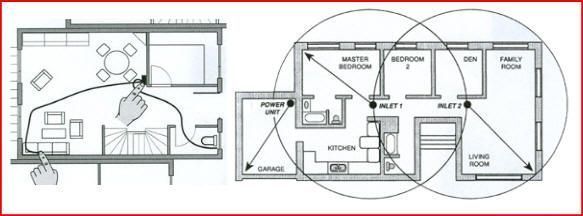
 Without a garage? You have a carport of just a parking bay near the house; you do not have to do without your central vacuum system! Install a vacuum inlet valve on the outside wall.
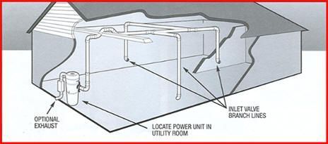
 A branch line connects the inlet line to trunk line. Attach a 90 degree elbow and run tubing from the inlet line to the trunk line. To align and measure the branch line, attach a 90 degree Tee fitting to the trunk line. Make sure the Tee connects with the air flow going toward the power unit. Align, measure, and mark the branch line for inserting it into the Tee fitting. Then, cut the branch line to length and insert it into the Tee. Check to make sure the cut is straight and even. Connect the next section of the tubing to the out-take side of the Tee fitting. Continue the trunk line until you come to another branch line junction point.
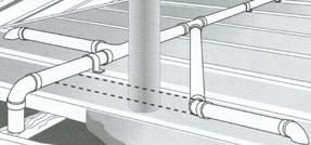 Continue to run the trunk line toward the power unit, connecting all branch lines as you go along. Again, make sure you connect all fittings with the air flow toward the power unit. Bring the trunk line to the access hole you have drilled for the power unit's intake tube. Place a 90 degree elbow over the hole and cut the trunk line to fit into this final elbow. Allow 5/8" of tubing to fit into the elbow's collar.
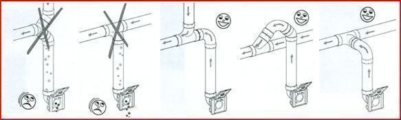
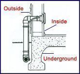 If the tubing is to be buried underground, dig a trench 12 to 18 inches deep along the side of the house. Fully assemble and test the tubing and low voltage wire before filling in the trench. It is recommended that the low voltage wire installed outside be encased in conduit which is available at most hardware stores. If the tubing is to run under the eaves, the tubing must be supported by pipe straps at least every 6 feet. On vertical sections, carefully snap-tie the low voltage wire behind the tubing.
 and make all the wiring connections after you have completed the tubing system. Of course, the inlet wiring must be run at the time the inlet tubing is threaded though the walls.
 insulate each connection with electrical tape.
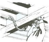


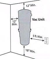
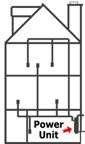
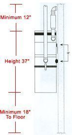 The power unit is screwed to the wall with the bottom screws of the mounting bracket about 48" up from the floor to allow convenient removal of the dirt canister. For proper motor cooling there must be at least 8" between the unit and the ceiling. If mounting on plaster or panel walls, be sure mounting bolts enter studs. If mounting on concrete wall, drill the wall with a masonry bit and insert plastic or lead anchors. As an alternative mounting on concrete walls, 2" x 4" studs or plywood may be suspended from overhead. With the power unit mounted, strip the low voltage wire and crimp into two "slip-on" terminals provided. Connect the main tube line to the intake valve on the unit. Do not cement this connection in case you wish to remove at a future date. For top loading units follow directions provided with unit.
Log In
Create New Account